Getting Started Guide
This is the Getting Started Guide for the SliceMK ErgoDox Wireless.
If you have questions regarding these instructions, please feel free to reach out.
It is highly recommended that users read this entire guide before attempting anything, even if you have prior experience with custom mechanical keyboards. The ZMK firmware setup process differs somewhat from other firmware options.
Assembly Safety Tips
- Wear surgical gloves or an anti-static strap when handling the circuit board (PCB) to minimize the chances of damaging the electronic components with electrostatic discharge (ESD).
- Avoid touching PCB components while the PCB is plugged in via USB. If you need to handle the PCB, always unplug the USB cable first (though it's fine to leave the battery connected).
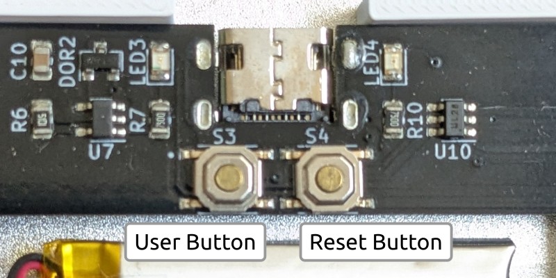
Keyboard Buttons
Each keyboard half has two dedicated buttons. To identify them, orient the keyboard such that the USB C port is facing you and the keys are facing up.
- The
reset button is on the
right of the USB port.
- Pressing the button once will reset/reboot the keyboard half.
- The keyboard LEDs will activate briefly after the reboot.
- Pressing the button twice within 500ms will put the keyboard half into
bootloader mode.
- The keyboard LEDs will be solid green while in bootloader mode.
- For a simple mnemonic, remember that "right" and "reset" both start with "r" and have 5 letters.
- Pressing the button once will reset/reboot the keyboard half.
- The
user button
is on the left of the USB port.
- The user button is primarily for turning the keyboard half off.
- After turning a keyboard half off, pressing keyboard keys will have no effect and consume no battery. It is a good idea to take advantage of this feature when traveling with your keyboard.
- Pressing the "off" button on a peripheral half will light the LED for one second as the keyboard turns off.
- Pressing the "off" button on a central half (in a dongleless setup) will immediately turn the keyboard off. Please be aware there is no visual indication implemented at the moment.
On the latest generation keyboard PCBs, the buttons are accessible externally. On the previous generation keyboard PCBs, the buttons are behind the bottom acrylic layer.
- Latest Generation
- Previous Generation
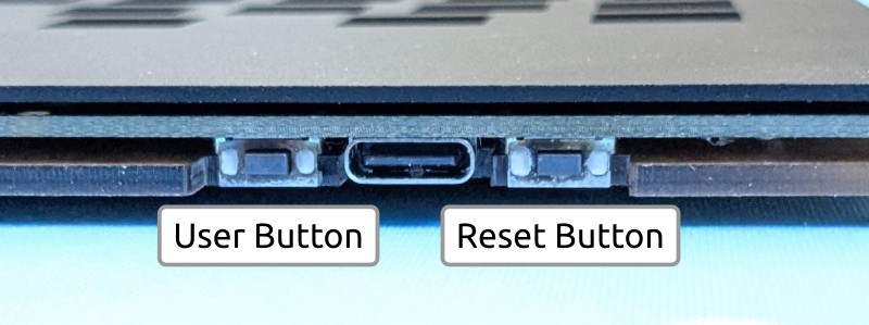
It's not necessary to remove the bottom acrylic layer if you need to press these buttons. The acrylic layer has holes, allowing you to press the buttons through the acrylic using a paperclip or similar tool.
Battery
Each keyboard half will ship with a battery installed and connected. In rare instances, the battery connector may come loose due to excessive force sustained throughout the shipping process. One quick way to confirm that the battery is connected is to press the reset button once with USB unplugged.
- If you observe LED behavior after pressing the reset button, then the battery is attached and functional. You can proceed to the next section.
- If there is no response after pressing the reset button, open the keyboard case and double check that the battery is fully "clicked" into the connector.
Users will generally never need to physically disconnect the battery. In the unlikely event that you need to do so, please be extremely careful as the connector is delicate. Excessive force can rip the connector off and render the PCB unusable. The proper way to disconnect the battery is to rotate about the top of the battery connector, like lifting a wheelbarrow.
Some PCBs may have multiple battery connectors for redundancy. Only one battery should be attached to a keyboard half at a time.
Initial Firmware
Keyboards generally ship with a "matrix testing" firmware preloaded. This firmware will turn on the keyboard LEDs when a switch is pressed. This provides an easy way of testing whether each switch has been installed correctly or if a switch pin was bent during insertion.
A small subset of keyboards is shipped with the production keyboard firmware rather than the testing firmware. This is likely the case if the battery is connected but no LED turns on when pressing the keyboard switches. If this is the case for your keyboard, please proceed with this guide but skip the "Peripheral Flashing" and "Initial ZMK/Central Flashing" sections.
Switch Installation
- If your keyboard came with foam preinstalled, loosen the screws slightly before installing the switches so the plate and PCB can realign if necessary.
- Start by installing switches in the corners. This ensures that the plate is completely aligned with the PCB before the rest of the switches are installed.
Bootloader Mode
To update the firmware running on a dongle or keyboard half, it should be connected via USB and put into bootloader mode. All dongles/keyboards are shipped with a UF2 bootloader. While in bootloader mode, you will see a virtual flash drive on your computer.
- The virtual drive for the dongle will be named
MDBT50QBOOTorNRF52BOOT(depending on the dongle). - The virtual drive for the keyboard halves will be
SliceMK.
Please avoid having both halves in bootloader mode at the same time. Since they
both use the SliceMK virtual drive name, it will be difficult to identify
which half is which if they are plugged in together. It's possible that only one
of the two drives will visible depending on your operating system.
Firmware files have the .uf2 extension. To flash a firmware file, simply copy
it to the virtual drive.
Please double check that you are flashing the correct file into the correct device.
- Make sure the firmware is for the correct dongle and/or PCB version.
- Do not flash the dongle firmware onto either keyboard half or vice versa.
- Do not flash the left half firmware onto the right half or vice versa.
A few notes about the UF2 bootloader:
- Depending on your operating system, you may encounter an ejection or file copy error. This is expected and not a bug.
- If you subsequently return to bootloader mode, the UF2 file that you copied earlier will no longer be there. This is expected; the bootloader drive is a virtual drive and merely a transport mechanism.
- If the virtual drive does not disappear after copying the firmware file, most likely there is a compatibility issue. You should double check that the firmware is for the correct PCB version.
Dongle vs Dongleless
The keyboard can be used without a dongle (dongleless) if you would like to prioritize convenience. The keyboard can also be used with a dongle if you would like to maximize battery life. For a complete comparison, check the Dongle vs Dongleless page.
If you are using a dongle, please place your dongle in bootloader mode and check
the INFO_UF2.TXT to determine the exact model. You will need this information
when later building your firmware.
UF2 Bootloader 0.6.3-44-g1c8da45 lib/nrfx (v2.0.0) lib/tinyusb (0.12.0-145-g9775e769) lib/uf2 (remotes/origin/configupdate-9-gadbb8c7)
Model: Raytac MDBT50Q-RX
Board-ID: nRF52840-MDBT50Q_RX-verD
Date: Apr  1 2022
SoftDevice: not found
The dongle model should be one of the following:
- Raytac MDBT50Q-RX
- Raytac MDBT50Q-RX Green
- Raytac MDBT50Q-CX Blue
Your dongle should be in bootloader mode when you plug it in for the first time. To enter bootloader mode afterwards, press and hold the dongle button while plugging in the dongle.
Once you have your keyboard fully configured, you can add a &bootloader key to
your keymap to make bootloader mode more accessible.
Split Communication
This section is purely informational. You do not need to take any action until the next section.
Before flashing the production keyboard firmware, it's important to understand how the keyboard halves communicate with each other and your computer.
If you are using a dongle:
- The dongle is the "central" and handles the keyboard logic. The two keyboard half "peripherals" will send data to it.
- When building the firmware with the keymap configurator, select your dongle as the "Build Target".
- Flash
zmk-dongle.uf2from the keymap configurator onto the dongle. Flashperipheral-left.uf2andperipheral-right.uf2onto the left and right halves respectively (these files are linked in the next section).
If you are not using a dongle:
- The left is the "central" and handles the keyboard logic. The right half "peripheral" will send data to it.
- When building the firmware with the keymap configurator, select the "Keyboard Left Half" option matching your PCB version as the "Build Target".
- You should flash
zmk-left.uf2from the keymap configurator onto the left half. You should flashperipheral-right.uf2onto the right half (this file is linked in the next section).
A few notes about the central/peripheral setup:
- When you make changes to your keymap, you only need to update the central (the
dongle if you are using a dongle, the left half if you are not using a
dongle).
- Generally, it's not necessary to flash the peripheral(s). The only exception is when there are changes to the wireless communication protocol, in which case it would be made clear in the firmware upgrade instructions.
- You cannot use a peripheral half directly. If you connect a peripheral half via USB, it will not output anything. Keyboard data always goes through the central.
Peripheral Flashing
If you have a dongle, please make sure it is not plugged in while flashing the peripheral halves.
Start by flashing the right keyboard half with the peripheral firmware:
- Connect the right keyboard half over USB.
- Place the right half into bootloader mode (see the
Keyboard Buttons section for how to do that).
- The keyboard LEDs will be solid green while in bootloader mode.
- A
SliceMKvirtual drive should appear on your computer. Open theINFO_UF2.TXTfile and identify the PCB version based on theBoard-IDline.UF2 Bootloader 0.8.0-25-g970cded lib/nrfx (v2.0.0) lib/tinyusb (0.12.0-145-g9775e769) lib/uf2 (remotes/origin/configupdate-9-gadbb8c7)
Model: SliceMK
Board-ID: nRF52833-slicemk-ergodox-202207-green
Date: Jan 8 2024
SoftDevice: not found - Download the
peripheral-right.uf2firmware (download page) matching the PCB version. - Copy
peripheral-right.uf2to theSliceMKdrive.- The keyboard LEDs will be solid red while the firmware is flashing.
- The keyboard LEDs will turn off when flashing is complete.
- Unplug USB cable for the right half.
If you are not using a dongle: please immediately continue to the "Keymap Configuration" section.
If you are using a dongle: please repeat the above steps with the left half
(using peripheral-left.uf2 where appropriate). Make sure to check the PCB
version again as it may be different for the two halves.
Keymap Configuration
You can configure your keyboard layout using the keymap configurator. When building the firmware, make sure to select the correct "Build Target". If you are using a dongle, that would be the dongle. Otherwise select the "Keyboard Left Half" option matching your PCB version of the left keyboard half.
For the initial build, keep the example keymap as is including the "testing" layer. This layer is designed to help you easily test that all your keys are working.
Initial ZMK/Central Flashing
If you are using a dongle (dongle is central):
- Build the firmware using the keymap configurator.
- Plug in the USB dongle.
- Place the dongle in bootloader mode. The dongle LED should pulse slowly while in bootloader mode.
- Copy
zmk-dongle.uf2to the dongle virtual drive. The dongle LED will flash very quickly while it's flashing. The dongle LED will turn off when flashing is complete. - Press a few keys on the keyboard halves. Give it a couple of seconds for them to bond with the dongle. Both halves should work after this step is complete.
If you are not using a dongle (left half is central):
- Build the firmware using the keymap configurator.
- Connect the left keyboard half over USB.
- Place the left half in bootloader mode. The keyboard LEDs should be green.
- Copy
zmk-left.uf2to the left half's virtual drive.- The keyboard LEDs will be solid red while the firmware is flashing.
- The keyboard LEDs will turn off when flashing is complete.
- Press reset once to reset/reboot the left half.
- Press a few keys on the left keyboard half. It should work like a regular USB keyboard.
- Press a few keys on the right keyboard half. Give it a couple of seconds to bond with the left keyboard half. Both halves should work after this is complete.
Key Testing
Use the "testing" layer to confirm that all the keys are working.
Keymap Modifications
Once you have confirmed that all the keys are working, you can delete the layer so the "main" layer becomes the default layer and build the new firmware.
To update the keymap:
- Place the central in bootloader mode.
- Copy
zmk-dongle.uf2to your dongle orzmk-left.uf2to your left half. - Press keys on peripheral(s) and give the central a couple of seconds to reconnect.
Each time you modify your keymap, make sure to keep a copy of the
slicemk_ergodox.json file from the build archive. You will need it to make
changes to your keymap. Your keymap will be automatically deleted from the build
server after a couple of hours.
Laser Cutting Paper
You should decide whether you want to leave on or peel off the laser cutting paper. Functionally it doesn't make much of a difference.
We recommend removing the laser cutting paper for the bottom acrylic layer as it is a bit nicer aesthetically and it makes the PCB version number visible without having to disassemble the case.
If your case includes foam, we recommend keeping the laser cutting paper on that as it provides a bit of additional height/cushion.
Rubber Feet and Tenting
- If you purchased a tenting kit, please use the designated holes to position
the rubber feet on the keyboard. They are there so you can detach the keyboard
and use it independently with the rubber feet still attached.
- You should place the rubber feet after you decide whether you want the laser cutting paper to remain on the bottom layer.
- If you are not using your keyboard with the tenting kit, the rubber feet placement is not important.